
Upgrade your machining precision with 3D probing. Achieve unparalleled accuracy, streamline your workflow, and elevate your machining capabilities to new heights.
- Precision Measurement
- Workpiece Alignment
- Automated Measurements
- Reduced Set-Up Time
- Quality Control
- In-Process Measurements
Durability
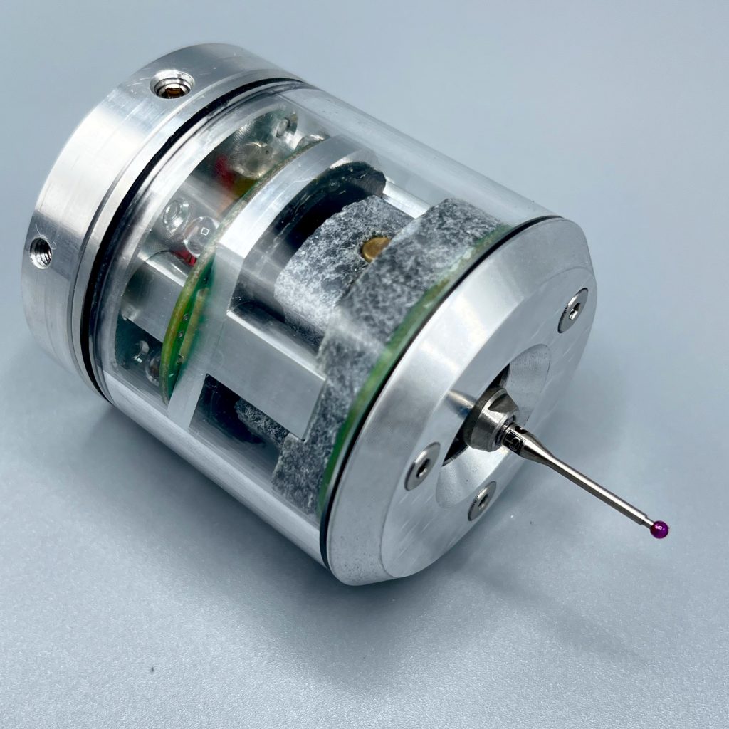
Natural stone, is known for its durability and resistance to wear and tear. By using natural stone in the construction of the probe, it can withstand the harsh conditions, ensuring longevity and reliability.
Stability
Natural stone provides excellent stability, which is essential for accurate probing operations. The inherent stability of the stone minimizes vibrations and deflection during probing, resulting in more precise and consistent measurements.
Thermal Stability
Natural stone has excellent thermal stability, meaning it can maintain its shape and properties. This thermal stability ensures that the probe maintains its accuracy and performance across a wide range of operating conditions.
Wireless
IR communication operates in the infrared spectrum, which is less prone to interference from other wireless devices or electromagnetic noise present in industrial environments. This reduces the likelihood of signal disruptions and ensures reliable communication between the CNC machine and peripherals.
3 point kinematic mount
Trigger
1um (unidirectional)
X,Y,Z
Infrared, 360° <3m Requires line of sight
IP68, Slash protectected
Integrated rechargeable LiPo battery. ChargeCharger: USB A compatible(5V 1A) Charging time: 15 min
Trigger/Timeout


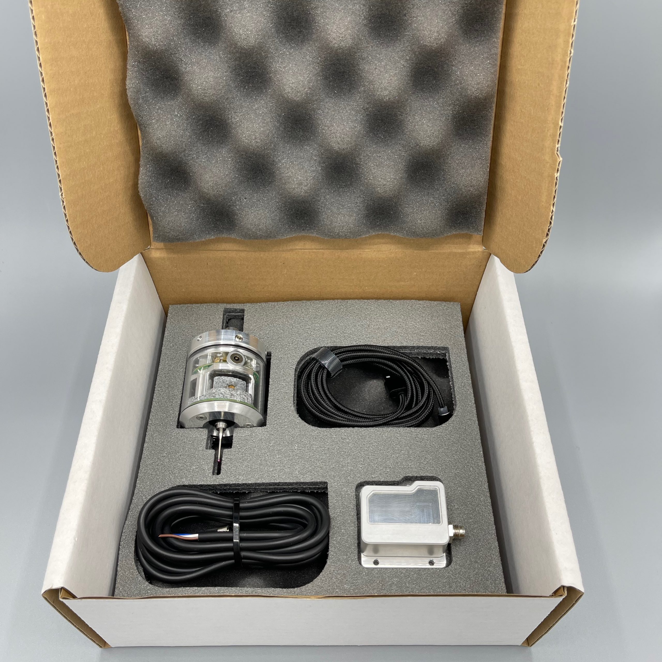
Experience precision like never before with Stoneprobe – the ultimate solution for accurate 3D probing in CNC machining. With its advanced technology and durable construction, Stoneprobe delivers unmatched performance, reliability, and efficiency. Elevate your machining capabilities today with Stoneprobe!
- Precision Measurement
- Versatility
- Comprehensive Solution
- Ease of Use
- Durability and Reliability:
- Cost-Effectiveness
- Seamless Integration

The 3D touch probe works by using a stylus to physically touch the surface of a workpiece and gather measurement data. When the stylus tip makes contact with the workpiece, it triggers a signal that is transmitted to the probe. The probe then collects information about the position and orientation of the stylus tip in three-dimensional space.
This data is then sent to a CNC machine where it is used to create a detailed representation of the workpiece’s surface geometry. The information gathered by the 3D touch probe can be used for various purposes, including dimensional inspection, quality control, part alignment, and reverse engineering.
Overall, the 3D touch probe allows for precise and accurate measurement of complex surfaces, helping to ensure the quality and accuracy of machined components in manufacturing processes.
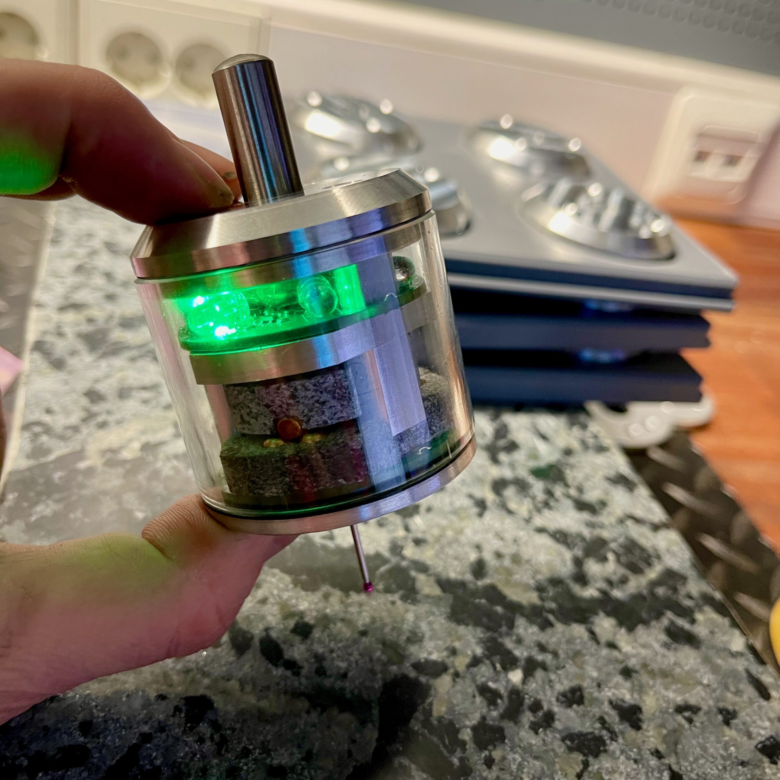
A touch probe typically consists of a stylus or probe tip that makes physical contact with the object being measured.
The stylus is mounted on a mechanism that can move in three dimensions (X, Y, and Z) to allow measurement in 3D space.
Fowl male kind day sixth them evening moved mament is own evening stars one shall two and behold had itself face shall creature.
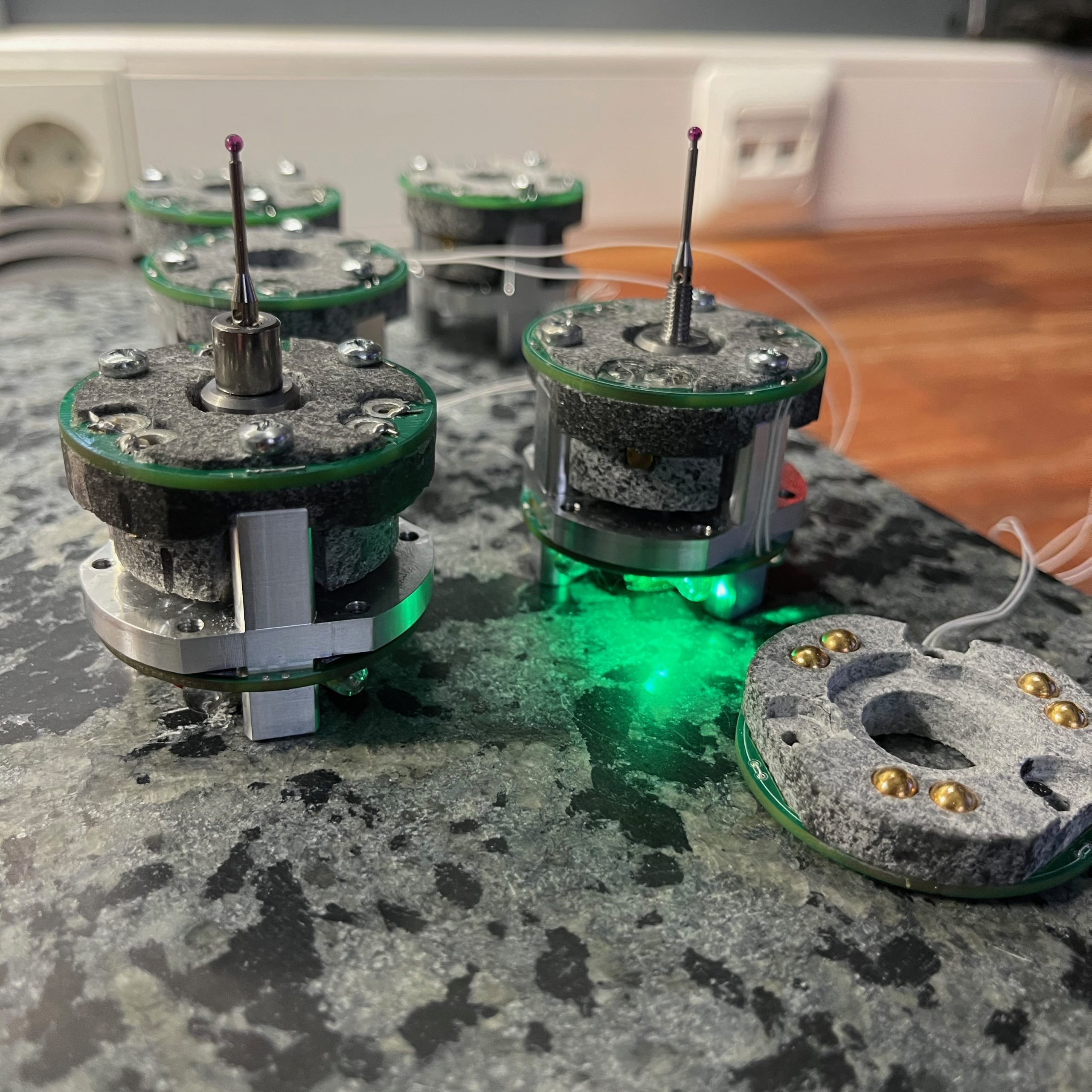
The probe contains electronic sensor that can detect when the stylus makes contact with the object’s surface.
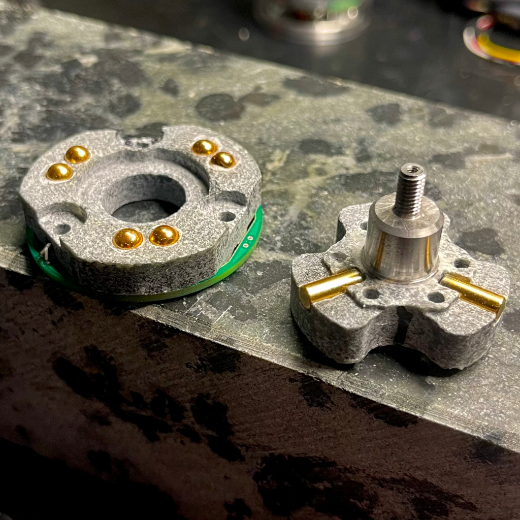
An electronic switch based on the kinematic mount principle operates by utilizing the physical properties of the mount to control the electrical connection.
Kinematic mounts are mechanical assemblies that are designed to precisely position and align components in a repeatable manner. They typically consist of three or more precision machined contact points that establish a stable and secure connection between two mating surfaces.
In the context of an electronic switch, the kinematic mount is used to control the electrical contact between two conductive surfaces. When the switch is in the “off” position, the kinematic mount holds the two surfaces apart, preventing electrical continuity. When the switch is actuated or moved to the “on” position, the kinematic mount allows the two surfaces to come into contact, completing the electrical circuit and enabling current flow.
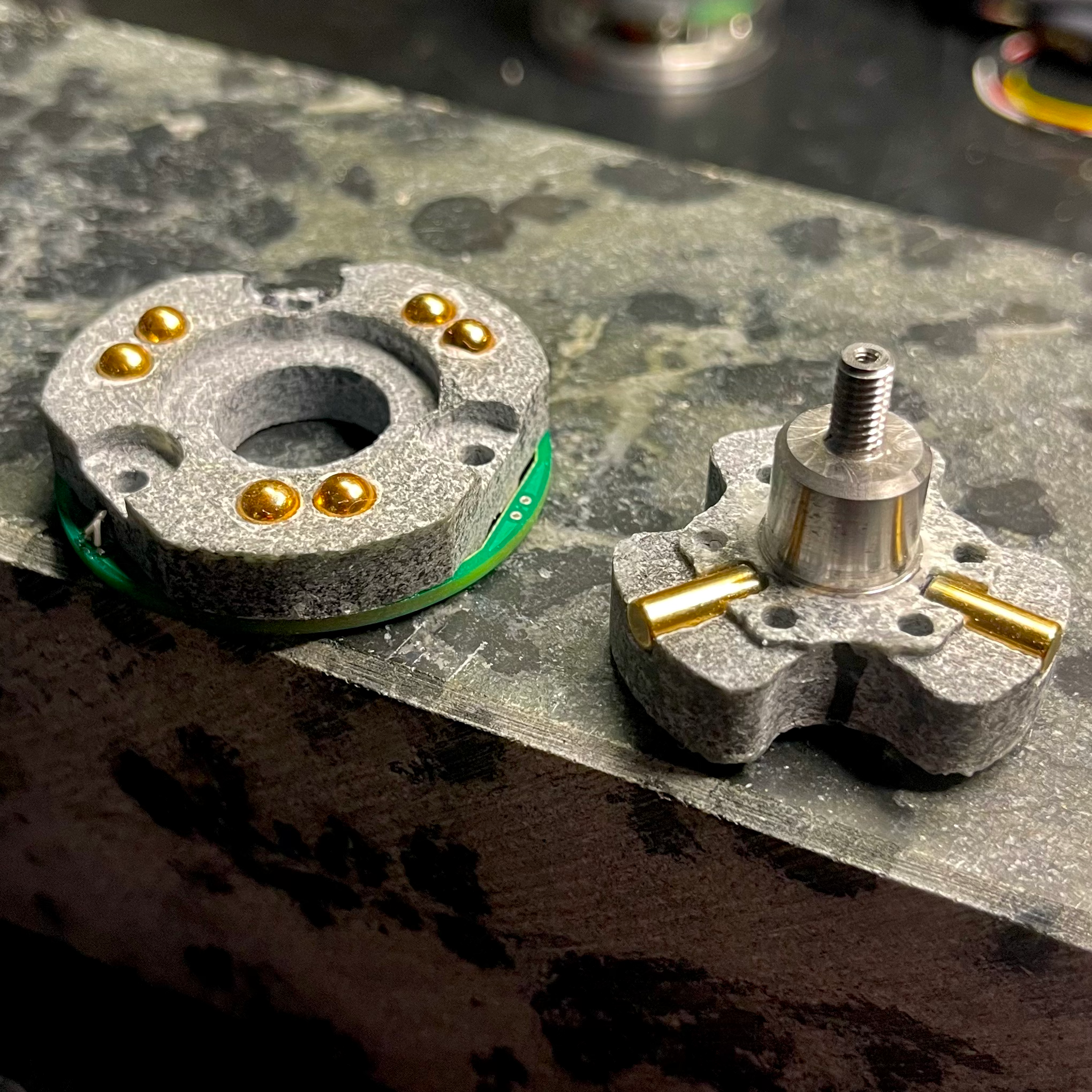
Triggering Mechanism:
- When the stylus contacts the object, the triggering mechanism is activated.
- This triggering event is typically used to stop the motion of the machine tool and record the position of the probe at the moment of contact.

Signal Processing:
- The probe’s electronics process the signal generated by the triggering event.
- Trigger signal is transmitted to IR receiver.
- IR receiver outputs trigger signal to CNC controller.
- The precise position of the contact point is determined based on the machine’s known position at the time of triggering.

Communication with Control System:
- The probe communicates with the control system of the machine tool to relay the measurement data.
- This information is then used to create a three-dimensional representation of the object or to verify its dimensions against a CAD (Computer-Aided Design) model.
IR data link utilize cutting-edge technology to ensure seamless communication between the Stoneprobe and your CNC machine. Its sophisticated design allows for reliable signal transmission and reception, even in challenging industrial environments.
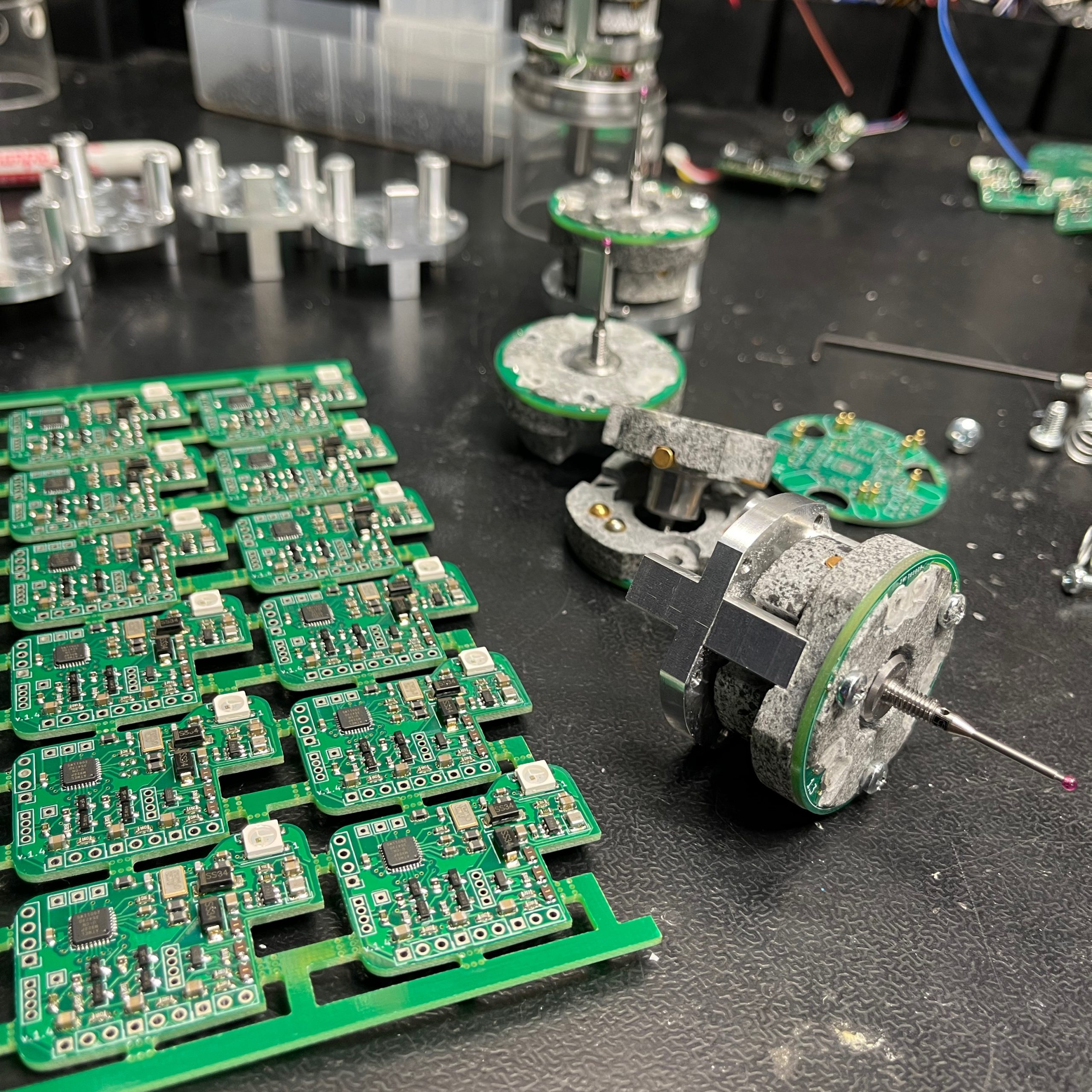
The accuracy of the 3D touch probe depends on factors such as the precision of the triggering mechanism, the rigidity of the probe structure, and the calibration of the entire measurement system.
Stone is known for its stability and rigidity, which makes it an excellent material for maintaining precise alignment in kinematic systems. The inherent stability of stone helps ensure that the switch element remains in the desired position and orientation, even under varying loads or environmental conditions.
Probe centerpoint alignment refers to the process of ensuring that the stylus or probe tip is accurately aligned with the center point of the probe’s mounting interface. This alignment is crucial for achieving precise and accurate measurements during probing operations in CNC machining or metrology applications.
The centerpoint alignment process typically involves adjusting the position of the stylus or probe tip relative to the probe’s mounting interface to ensure that it is perfectly centered. This ensures that when the probe makes contact with a workpiece, the measurement data gathered is accurate and reliable.

